Concrete NDT Inspection
The construction of modern facilities and their further operation are often faced with the solution of rather complex engineering problems associated with the conditions of interaction between the structure and the geological environment. The article discusses the possibility of using geophysical methods that have proven themselves in the solution of engineering and geological surveys and geotechnical survey. The general issues of diagnostics of building structures and options for solving specific problems during their examination are considered.
1.Introduction
Recently, in the practice of modern construction, considerable attention has been paid to the development of methods for the non-destructive testing of concrete structures. This is primarily due to the increased requirements for the quality of concrete for the construction of new buildings and structures, which is due to the development of monolithic construction technology, as well as an increase in the size and complication of the shape of the structural elements used.
At the same time, the number of structures requiring major repairs is growing every year, which also implies the use of non-destructive testing methods for the rapid assessment of the accident rate and localization of weakened zones that require special attention.
In the practice of examining the state of concrete and reinforced concrete structures, ultrasonic ones occupy the main place among non-destructive methods. Today, portable ultrasonic equipment is used in world practice. It includes ultrasonic tomographs and borehole complexes, which allow studying the propagation of longitudinal, transverse and surface waves in a wide range of ultrasonic frequencies (from 20 to 100 kHz).
Along with ultrasonic methods, when examining concrete and reinforced concrete structures, GPR methods are widely used, which are somewhat inferior to ultrasonic methods in resolution but surpass them in productivity and depth of investigation. The main problem of ultrasonic methods is their low depth of investigation (1.0–1.5 m) during surface surveys and end-to-end sounding. With a higher power of the concrete structure, borehole ultrasonic measurements can be used, but this method can no longer be attributed to non-destructive methods.
The complex of geophysical methods, quite successfully used in Russia, includes such wave methods as ultrasonic, acoustic, and ground-penetrating radar. Today, a huge experience has been accumulated in the practical application of these methods for the control of building structures. And many Western countries have adopted and standardized them at the state level.
2.The main tasks solved when examining concrete structures using the GPR method
The list of tasks that can be solved using the GPR method is as follows:
1.) Determination of the thickness of the structure.
2.) Determination of the depth of the reinforcement (thickness of the cover).
3.) Determination of the reinforcement pitch.
4.) Search for areas of reinforced concrete structures where reinforcement corrosion is observed.
5.) Continuity assessment, detection of defects (cracks, cavities, inclusions, etc.) in the concrete structure.
6.) Detection of hidden engineering networks.
7.) Assessment of the contact conditions of the structure with the enclosing soil mass.
These tasks can be solved using high-frequency antennas in the 700-2500 MHz range; in some cases, a 400 MHz frequency antenna can be used.

The most convenient for solving most of the issues are specialized devices – Construction Scans 1700 (2500) 3D+ (Fig. 2).

The device has the following advantages:
1.) The entire device, including its computer, monitor, and power supply, is placed in one housing;
2.) The device is equipped with a marking mat with barcodes and readers;
3.) The firmware provides a mode of automatic recording of profiles by a signal from the barcode scanner;
4.) The built-in computer provides processing, display on the monitor, and archiving of scan results;
5.) Communication with the computer via a USB port, no additional drivers and settings are required;
6.) Built-in 5″ high brightness TFT color display;
7.) Laser direction indicator;
8.) Built-in displacement sensor;
9.) Built-in SD card slot;
10.) Quick-detachable battery.
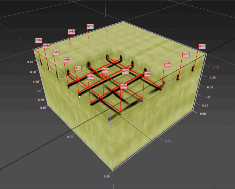
The device is equipped with specialized software that allows primary processing of radar data, automatic search for local and linear objects, and construction of 3D models of the surveyed area (Fig. 3).

3. Corrosion of reinforcement
For many reinforced concrete structures, the corrosion process of reinforcement determines the durability and efficiency of its operation. This process determines large economic losses during the operation of reinforced concrete structures. When steel corrodes around the reinforcement, a crust of iron oxide is created, which begins to grow inside the concrete. It can reach a 2 to 6 times higher volume than a part of the reacted reinforcement. This creates a radial tensile internal stress that is large enough for the formation of micro and macro cracks. This build-up of corrosion leads to an increase in the volume of the reinforced concrete structure, which is sometimes referred to as “oxide blistering”. When the internal tensile stress exceeds the ultimate strength of concrete, destruction occurs (Fig. 4).

Summarizing the above provisions, the applied task of reinforcement corrosion detection can be divided into three stages:
1. Determination of the depth of reinforcement (cover thickness);
2. Determination of the reinforcement pitch;
3. Search for abnormal areas associated with corrosion.
This problem is especially acute when studying large areas of structures, for example, foundation slabs. Therefore, the technique for searching for abnormal corrosive areas should be able to quickly cover large areas and be easy to learn by specialists of a wide engineering profile. Such conditions can be fulfilled by GPR. Detection of areas of reinforced concrete structures affected by corrosion can be performed based on the results of GPR survey using the attribute analysis program, which is an addition to GeoScan32. An example of detection of areas affected by corrosion is shown in Fig.5.

Attribute analysis is an analysis of the dynamic properties of a GPR signal. The following two types of attributes can be used to interpret GPR data: attributes related to dielectric constant; attributes associated with absorption of electromagnetic waves. When interpreting GPR data, the values of attributes calculated from the direct transmission signal, from the signal reflected from the base of the slab, and along the entire GPR track can be used.
The use of attribute analysis allows you to solve a number of problems when examining reinforced concrete structures. As an example, let’s consider the problem of finding sections of additional reinforcement for a foundation slab. Foundation slabs usually have two-layer reinforcement. In the case given, a 2-meter-thick slab in the places where the columns were installed was reinforced with a third row of reinforcement. It is not possible to solve this problem using 1700 MHz antennas due to the large thickness of the slab. However, the use of a 400MHz antenna in the variant of electromagnetic profiling and determination of the attribute of the weighted average signal frequency in the time interval before 8the appearance of the reflected signal, makes it possible to distinguish this section by the nature of the sharp drop in frequency (Fig. 6).

4.Assessment of the continuity and homogeneity of reinforced concrete structures
The most common task when examining reinforced concrete structures is to search for voids and cracks filled with air or water. Cavities and cracks filled with water are best displayed on radar profiles. This is due to the high contrast of these borders. Cavities filled with air are displayed much worse. Fig. 7 shows an example of using attribute analysis to detect air ducts in the walls of a building.

The following example shows the capabilities of the GPR for searching and studying various elements of the structure (Fig. 8).

Quite often, it is necessary to determine the strength characteristics for large-area reinforced concrete structures. In particular, for the normal operation of the foundation slab, the coefficient of variation of the tensile strength measured by the direct method should be no more than 13-16%. This can require a very large number of time-consuming and costly testing.
To reduce the number of tests, it is advisable to measure the strength of concrete in two stages: to determine the zones with homogeneous concrete and then, within the allocated zones, to clarify the strength of concrete by standard methods. It is proposed to assess the homogeneity of concrete by the method of GPR profiling according to the method developed on the basis of domestic equipment. The technique consists in searching for regions close in dielectric permittivity or conductivity. With a large number of field measurements, the processing of the results of GPR profiling can be easily automated. This problem is solved by defining and analyzing the attributes of the electromagnetic field. Stable correlations between the strength characteristics of concrete and various attributes were obtained in laboratory conditions. The allocation of homogeneous zones of concrete is carried out depending on the specified coefficient of variation of the determined parameter (Fig. 9).

GPR profiling allows in practice to implement with minimal cost a dense network of field measurements. With this information, strength tests can be more targeted. As a result of this approach, the labor intensity of the survey can be significantly reduced and the reliability of the results obtained can increase.
5.Assessment of the contact conditions of reinforced concrete structures with ambient ground
The assessment of contact conditions is quite relevant and is especially necessary for the correct operation of foundation slabs and tunnel lining. To assess the contact conditions and detect defects at the contact site, a complex of acoustic and GPR methods is usually used. GPR methods work well in cases where defects are filled with water and can be used independently.

Both visual interpretation methods and various methods of attribute analysis can be used to detect cavities under foundation slabs and behind tunnel lining. The following example demonstrates the capabilities of the GPR in detecting a void behind the tunnel lining (Fig. 11). Observations were made through an adjacent wall of parallel railway tunnels, one of which was partially filled up.


”Signal energy” attribute

Fig. 11 Determination of contact conditions through a railway tunnel wall
Assessment of the state of contact of a foundation slab with a subgrade is a fairly common task in the practice of residential and industrial construction.
Based on the results of areal GPR surveys, a map of various dynamic attributes of a GPR signal can be built. The example in Fig. 12 shows a map of the maximum spectral signal amplitudes, the value of which depends on the state of contact between two environments.

6.Conclusion
As already noted, the main advantage of GPR surveys is high productivity and, accordingly, high efficiency of obtaining information. Non-destructive testing of concrete structures is carried out to a greater extent by a complex of methods – ultrasound, seismic acoustics, ground-penetrating radar. Ultrasound and seismic acoustics make it possible to determine the deformation and strength properties of concrete, GPR – water-physical properties. The use of dynamic signal attributes allows automating the processing and interpretation of the result. A rational combination of a set of methods makes it possible to minimize the use of labor-intensive methods and make the use of direct (destructive) methods of concrete control more targeted.
About author:
Vladimir Kapustin
PhD in Physical and Mathematical Sciences
Junior Researcher at the Moscow State University