Developing GPR Surveys, Data Processing and Interpretation Techniques for Criminal Gravesites Location
Abstract – The authors of this article investigated several issues concerning the testing of GPR surveying and the development of data processing methods for assisting in solving criminal activities as performed by Investigative Committee of the Russian Federation.
The work of governmental agencies along with forensic science are deeply based on using GPRs for detecting caches, crypts, conduits and saps/ and , as well as buried explosives and bombs.
This research contains general requirements for field work while surveying buried objects. The authors specify requirements for equipment to be used, how the processing of obtained materials should be managed, and, finally, what interpretation methods should be utilized. Various tools used in these specific areas were analyzed in cooperation with experts of the Russian Investigative Committee.
This paper contains information on tests performed using OKO-3 GPR device equipped with AB-400M3 aerial (central frequency 400 MHz), aimed at locating various objects, such as: metal sheet, metal pipe, concrete block, plastic tank filled with water, wooden log, and animal bones package (imitating organic burials).
The article provides experimental material obtained and processed using these techniques. Measurements were tested over several stages. This type of monitoring not only allowed to trace signal’s alterations, but also to observe and analyze the potential rearranging of the soil’s physical properties over time, depending on its density and moisture.
This technique predisposes a GPR survey accomplished along an orthogonal observation grid with regular pitch between profiles, which allowed for further usage of represented data for 3D analysis. The authors suggest using a vast range of programming facilities for 3D-visualisation in programs of proprietary development.
The results of these geophysical operations, in accordance with developed techniques, are represented in the object’s location plan with determined depth of its positioning. The investigated technique of using GPR surveying to uncover underground criminal activities, including explosives, proved to be highly successful and has thus been requested by law enforcement agencies.
Keywords – criminal gravesites, GPR data processing
I. INTRODUCTION
At present GPR techniques are widely used for the following tasks: customs checks, SAR (Search And Rescue) operations and criminal investigations.
Moreover, low enforcement authorities have singled out GPR techniques as single and separate approach while criminal investigations. Tasks solved include search and identification of various objects, including caches, crypts, conduits, saps, criminal gravesites, buried explosives and IEDs (Improvised Explosive Devaces), which seem actual.
Several papers on the same subject have been published so far [2], [5], [6], though the published data were rather fragmented and never helped to produce a single algorithm. Our experts, jointly with their experts from the Investigative Committee of the Russian Federation managed to produce a single technique aimed at providing field operations, as well as field data interpretation.
Pre-requisites for effective GPR use in criminal investigations are based on the differences between undisturbed and/or disturbed soil ground, as well as between soils and solid inclusions, i.e. IEDs.
In this paper the authors propose general requirements for field operations while investigating an assumed area of local objects burial, equipment requirements, and field data processing and interpretation. Also, several aspects of joint instrumental search for specific local objects by GPR experts and CSI team are proposed. Test operations using OKO-3 GPR device equipped with AB-400M3 antenna unit (central frequency 400 MHz), produced by GK Logis- Geotech (Moscow, Russia), are discussed.
II. TESTING GROUND SETUP
While developing a technique for investigating an assumed area of local objects burial, it is crucial to setup a testing ground, which will either have real buried objects, or their imitators, buried at appropriate depths. Moreover, later on it could be used for CSI (Crime Scene Investigation) experts training.
To develop the technique, the authors selected a rectangular area of 6×8 m, i.e. 48 m .
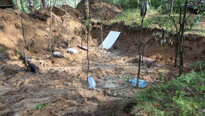
Soil ground – sand and sandy loam. Several local objects were buried at depths from 40 to 120 cm (Fig. 1), including: tilted metal sheet (40 to 100 cm), iron pipe (dia.10 cm, 150 cm long, burial depth 30 cm), upturned half of metal barrel (burial depth 100 cm), PVC bag filled with animal bones (burial depth 40 cm), water-filled plastic bottle (9 liters, burial depth 80 cm), 9 liters empty plastic bottle (burial depth 80 cm), packs of white and fawn block-stones (10 pcs. each, 200х70х100 mm, burial depth 60 cm), concrete block (burial depth 60 cm), timber log 150 cm long (burial depth 80 cm).

Fig. 1. Local objects setting within the testing ground
Field measurements within the testing ground were performed both immediately after their burial and, also, after some time. This type of monitoring helps not only to trace reflected signal changes, but observe and analyze ground soil characteristics redistribution vs. time, depending on its compaction and dampness. Analyzing field data obtained while field testing, optimal data processing and interpretation flows were selected.
Appropriate for the Investigative Committee experts local objects location technique could be separated into three basic phases:
· preparatory stage (field data gathering and preprocessing; hardware in-control testing; surveying, monitoring and grading weather conditions; selection of aerial unit and acquisition parameters);
· field (location GPS survey; surface conditioning; GPR survey; field data preprocessing);
· analysis (field data processing and interpretation; CSI excavation decision).
III. BASICS
A. Data Acquisition
Data acquisition technique should be planned at the initial stage of field operations, basing on the currently available data [6]. It is principal to get as much as possible information on the local objects’ size and location, burial depth, etc.
Success rate of criminal gravesites location is widely dependent on the processes of organic remnants decomposition, which depends on local weather and the environment. For example, in the medium climatic zone an organic object is usually subject to putrescent changes leading to complete skeletization of the remains.
Otherwise, in the dry climate and ventilated soils, we will observe organic remains mummification. Also, chemical changes of the body will run faster.
Moreover, substantial impact on buried remains decomposition is subject to clothes availability and/or wrapping of the body before burial. Also, the available synthetic outer garments could diminish body decomposition and ground spillage into ribcage. Decay processes of organic remains usually led to in situ cavitations formation, which could be easily detected using GPR techniques.
АB-400 400
АB-700 700 ≤3 0.1
B. Weather Conditions
It is crucial to consider weather conditions before starting field data acquisition. Best conditions for GPR surveys are in summer, when it is dry (or 2 – 3 days after it rained). Otherwise – in winter, over dry and frozen soil. GPR scanning over moist or snow-melting grounds may not do, since they cause substantial signal attenuation and reduction in the antenna unit depth penetration, which dramatically hamper local objects’ image quality.
C. Surface Conditioning
Before starting the survey surface of the surveyed area should be pre-conditioned, i.e. leveled off by hay-moving and brush cutting, also, all foreign items which could hamper close contact between the antenna unit and the soil surface should be removed. In winter, snow cover of over 100 mm thick should be either removed or compacted.
D. Equipment Mobilization and Servicing
Before starting the survey, the field team should mobilize ancillary equipment which can help while searching for the local object (powered auger, spit, portable gas sniffer, etc.). Also, 24 hours before equipment mobilization functional check-out of the field equipment should be made, including batteries checks and charging, preliminary GPR assembly and settings adjustment.
E. Select Antenna Unit, Data Processing and Interpretation Parameters, Acquisition Geometry
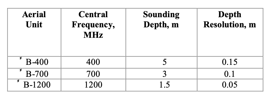
Antenna frequency should be selected in accordance with the survey depth and running dimensions of the local object. In case of locating an object buried at approximately 1.5 meters depth, the task could be solved using deep-penetrated antennas, i.e. either AB-700, or AB- 400М3 units (Table 1). Anyway, aerial’s resolution should be considered. In our case we speak about both – depth or areal resolution of the unit. Thus, successful search is based on the local object’s size, which should exceed unit’s depth resolution.
TABLE 1. MAXIMUM SOUNDING DEPTH AND RESOLUTION FOR THE OKO-3 GPR ANTENNA UNITS, CALCULATED FOR LOW-LOSS MEDIA
Here it is important to select acquisition geometry vs. local object’s location and observation interval along the selected line. In case of stretched objects observation lines should be oriented crossways towards the assumed local object’s location. In this case the hinted object could be located via specific reflection of the diffracted feature (hyperbolic hill).
A set of parallel survey lines is obsolete to locate local objects. Moreover, adjacent lines should be close to the lateral size of the local object. Grid spacing depends on spatial resolution of the aerial unit. Thus, the inter-trace space should be selected in the way to partially overlap the available Frensel regions. Also, the inter-trace space depends on GPR unit path velocity and varies from centimeters (while studying minor local media changes and locating local objects) to dozens of centimeters.
OKO-3 GPR equipped with АB-1200М3 and АB- 400М3 antenna units was used while developing this technique, with the following field characteristics, which the authors supposed as optimal:
· Samples amount – ≥ 511;
· Time scale – 50 – 100 ns, for АB-400М3, and 24 – 48 ns for АB-1200М3 units;
· Stack – 8 – 16 aimed at average operator’s speed of 3 –4 km/hr;
· Trace spacing – from 30 mm up to 100 mm;
· Gain profile – exponential, gain ratio 50 –100;
· Scanning mode – by movement, using DP32 moving sensor.
F. Area Mark-out and GPR survey
Site layout (draft), along with its tie-in to the available site sketch are must-have, as well as line-pegging and separate profile tie-ins.
Before starting field work, rectangular site should be laid out using pegs and tight rope (cord) to set the perimeter. The technique implies GPR survey within the orthogonal survey grid with regular pitch between the profiles, which provides collection of adequate field data and their uniformity for further analysis using proprietary 3-D visualization software. For the local object of 50 to 150 cm linear size, regular pitch should be within 30 to 50 mm range. Each profile is traversed linearly, along the tight rope.
It is obligatory to fill-in a field log while field operations, as well as photo- and video fixation of the activities. It should contain: number of the traversed profile, its location and direction. Also, it is important to tag the radargram and note tag numbers and object description in the field log (i.e. corner of a building, changes in covering type, etc.).
G. Data Preprocessing, In-Field Data Analysis
It is recommended to run preliminary field GPR data processing right on the spot to make sure that:
· set acquisition parameters were adequate to obtain high-quality data;
·time scale is adequate to obtain appropriate scanning depth;
· no lines were omitted while GPR scanning and no frequency hops of direct signal occurred;
· before starting the survey dielectric permeability was set correctly.
In case of poor field data quality due to incorrectly set scanning parameters, the operator should re-run either several profiles, or repeat the whole survey.
Then, line data preprocessing should be carried out by selecting characteristic reflections (hyperbolas) from local objects; abnormal areas in the plot, specific for trenched soil, or disturbed soil uniformity (i.e. available voids, specific jingling type of records). Points of interest should be marked with pegs and/or pennants. In case several abnormal areas were detected in the radargram, all of them should be marked out with appropriate scribe marks. Then, a decision on preliminary excavation should be taken (i.e. search for local organic object in the soil using entrenching tools, probing rod or gas sniffer). Also, these spots could be checked with powered auger by drilling 3 – 5 holes. In case of organic burial, the auger usually recovers pieces of clothing, bones, etc. In cases of decomposition process still under way, specific smell will be the indicator.
H. Field Data Processing and Interpretation GeoScan-32 Software (produced by ООО Logis)
Using
Upon completion of the field work, all radargrams are subject to table-top testing using either a desktop workstation or a notebook with pre-installed GeoScan-32 software package.
Basic principles of GPR data processing include, first of all, selection of desired signal form contaminating signals and background noise [3], [4]. Specific algorithms of signal transformation help to attenuate and\or eliminate contaminating signals and background noise and boost desired waves.
Data processing includes the following procedures:
1) scale and profile length correction, and profile coordinates setup (Fig.2);
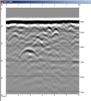
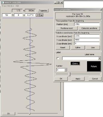
Fig. 2. Initial radargram (a), line characteristics field, where profile coordinates are set (b)
2) data visualization parameters (scale, brightness, contrast) setup;
3) gain parameters setup (to provide a full-length contrast record) (Fig. 3);
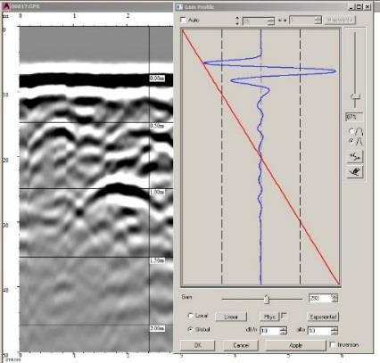
Fig. 3. Using linear gain factor.
4) mean value subtraction (used to eliminate possible common-mode interference and feedthrough signal) (Fig. 4);
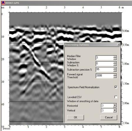
Fig.4. Mean value subtraction for all lines (accuracy – 95%)
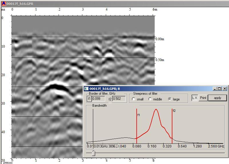
5) band-pass filtering (to improve S/N ratio) (Fig. 5);
Microsoft Word – Developing GPR Surveys
Fig.5. Band-pass filtering. Band pass range is set at the desired signal frequency
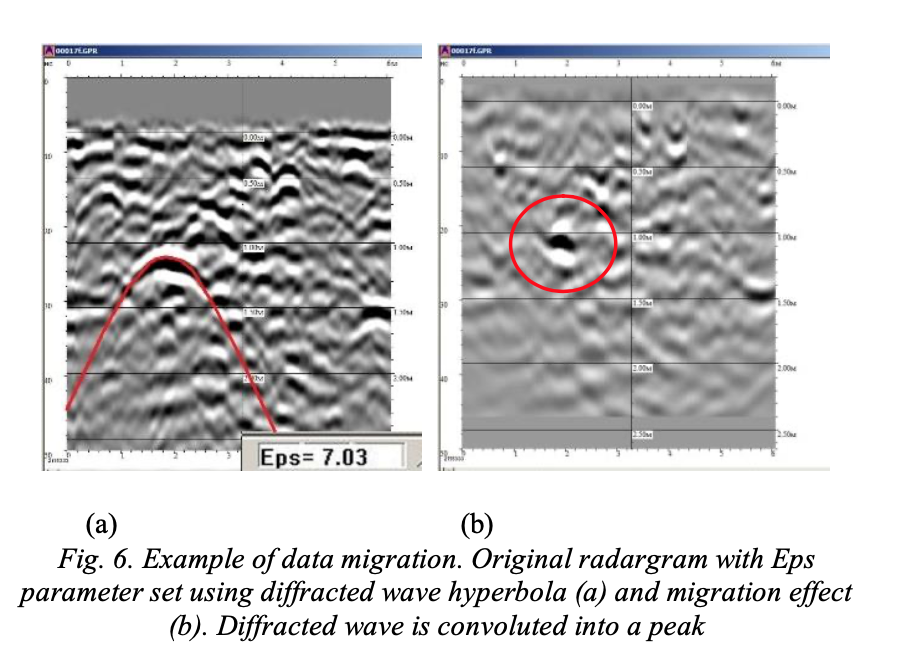
6) data migration (for objects localization; to be used only when dielectric permeability was set correctly using diffracted wave hyperbola) (Fig. 6);
Microsoft Word – Developing GPR Surveys
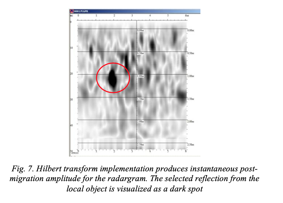
7) envelope discrimination (Hilbert transform, instantaneous amplitude) (Fig.7);
8) 3-D model buildup utilizing all available in- and cross-lines using GeoScan-32 and/or Armscan 3D software;
9) color palette selection for local objects visualization at the target depth (3-D block section) (Figs. 8, 9).
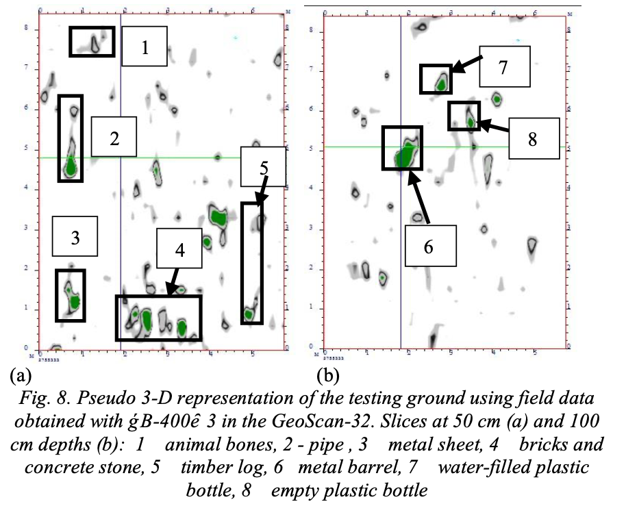
The idea of the proposed GPR technique field testing was to obtain high-quality representation of the testing ground with the selection of buried local objects, with actual burial depths.
Obtained field data showed that reflections from metal objects (metal sheet, barrel, pipe), bricks and concrete stone, water-filled plastic bottle and PVC bag filled with animal bones could be picked up quite easily, either just after the burial, or within the substantial time lag. Anyway, detecting reflections from timber log and empty plastic bottle were confusing due to electromagnetic signal attenuation in the hydromorphic sand, and signal dissipation in the near-surface. Therefore, additional studies will be needed to localize these types of local objects.
IV. CONCLUSION
The proposed technique of GPR field surveys, field data processing and interpretation implemented in the testing ground, helped us to develop CSI teams operation routines while criminal gravesites location. It can help while fast in-field location of criminal burials while CSI team operations.
Upon GPR studies CSI people can start particular excavations revealing criminal gravesites and allowing appropriate procedural implementation (drawing up protocols, etc.)
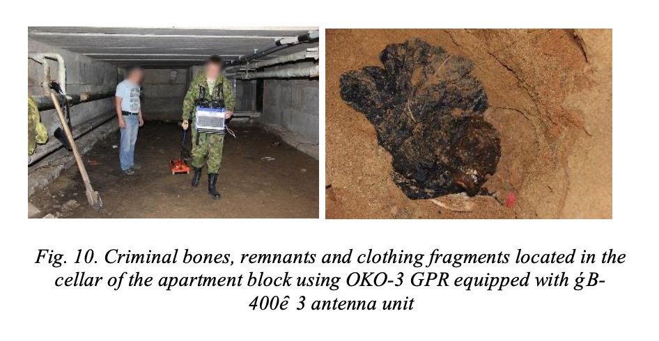
In the last 9 months of 2015 OKO-3 GPR unit (along with appropriate software support) have been widely used in CSI operations. In 60 out of 65 extremely grievous crimes either criminal gravesites were discovered, or profound prosecution evidences have been discovered (Fig. 10).
Therefore, using our testing ground we managed to show that our GPR technique is quite efficient in solving specific tasks of CSI units while criminal gravesites location.
REFERENCES
[1] https://sledcom.ru/press/smi/item/507518
[2] John J. Schultz Detecting Buried Remains in Using Ground-Penetrating Radar, University of Florida, 2003, 542.
[3] GroundPenetratingRadar,EditedbyDavidJ.Daniels, Second edition, 2004, 761.
[4] Ground Penetrating Radar Theory and Applications,
Harry M. Jol, First edition, 2009, 508.
[5] B.Rudakon, D.Brashnikov, A.Schukin, Specialized equipment of Internal Affairs Agencies, Tyumen Institution of Futher Training for members of the Minisity of Interior Affairs of the Russian Federation, 2014, pp.354.
[6] N.Dudin, The book of Investigator, The Academy of The Prosecutor General’s Office of the Russian Federation, St.Petersburg, 2008, pp.170.
[7] M.Vladov, A.Starovoytov, “Introduction to Georadiopositioning”, Moscow State University, 2005, pp.153.
AUTHORS
N. Pudova, А. Urusova, М. Shirobokov – Research&Survey Institute Geotech
А. Marchkov – Investigative Committee of the Russian Federation