GPR technologies in the road industry
Maintaining highways in good working order requires timely and efficient types of repair work. Based on the diagnostic results, a full range of quantitative characteristics of road sections is obtained: the modulus of elasticity on the surface of the road structure, the coefficient of adhesion, the evenness of the surface, etc. However, they reflect only the state of the surface of the structure, without answering the question of what are the underlying causes of the appearance of defects in the road structure. Generally, the most common repairs are clearing drainage ditches and pavement reinforcement. Strengthening pavements is an expensive undertaking. Still, according to studies of specialists dealing with these issues, all this gives only a temporary result for 2-3 years, since very often the very cause of subsidence and cracks is not determined and defects reappear on the new coating.
GPR is used in the survey and design, construction, reconstruction, repair, and maintenance of highways. GPR is equipment that allows determining the thickness of the structural layers of the pavement, as well as the internal structure of the soil environment in the form of continuous soil-hydrogeological sections to a depth (depending on the central frequency at which the device operates) from 0.5 to 30 m respectively, with a resolution capacity of 0.005 to 0.5 m. In this case, the number of drilling operations is significantly reduced, since only control drilling is performed.
The tasks solved using GPR technologies in the road industry:
1. Surveying and designing highways:
• survey of soil and hydrogeological conditions of the area;
• determination of the position of the groundwater level;
• assessment of the depth of a reservoir or river in the place of the future bridge crossing and setting the geometrical dimensions of the channel bottom;
• determination of the location and size of utilities;
• exploration and assessment of reserves of useful strata of materials and soils in open pits;
• assessment of the impact of roads on the environment (e.g. when crossing swamps), etc.
2. Scientific support of road construction projects:
• prospecting and determination of reserves of road-building materials and overburden rocks in near-highway quarries;
• installation of the remaining reserves of useful strata in open pits during construction;
• assessment of the thickness of the layers of the newly built road structure;
• monitoring the density and moisture content of the laid materials;
• determination of ice thickness on technological roads and winter roads, etc.
3. Reconstruction and repair of highways:
• inspection of existing highways and identification of the cause of the destruction of road sections;
• determination of the thickness of the old road surface for subsequent regeneration;
• assessment of the continuity of the culvert along the path of water infiltration in the soil through the joints of the culvert links;
4. Road maintenance:
• determination of the bearing capacity of road structures through the thickness of the layers and the moisture content of the subgrade soils;
• predicting the position of the sliding curves and the possible violation of the stability of the slopes of the embankments;
• assessment of the homogeneity of the subgrade soil;
• monitoring the behavior of road structures;
• assessment of the rate of freezing and thawing of the subgrade during the thaw period, etc.
High-performance, non-destructive, and environmentally friendly GPR technologies can significantly reduce construction and operating costs. At the same time, the reliability of road structures is significantly increased due to the high reliability of the initial geological information. According to experts and scientists working in the road industry and having extensive experience in the application of GPR technologies, the time has come when GPR works can be included in every project of construction, reconstruction, and repair of highways.
Principle of operation
GPR technologies are based on the phenomenon of reflection of electromagnetic waves from surfaces (boundaries of pavement layers), on which the electrical properties of the environment (materials from which the pavement layers are made) change. The main parameter of the environment is its dielectric constant (ε). The higher the contrast of the values of dielectric constants, the more clearly the boundaries of the environment are distinguished, the electromagnetic wave in the soil (or other research environments) is reflected from the boundaries of layers with excellent dielectric properties. The structure of the GPR includes emitting (source) and receiving (receiver) antennas. The source emits an electromagnetic wave of a given frequency in the form of a finite one and a half period impulse. At each point of the distance, a track is recorded – the dependence of the signal amplitude on the time of arrival of the reflection. A set of tracks along the entire distance makes up a radarogram.


A GPR consists of several main units:
1. the control unit – here the receiver and the transmitter are synchronized and the samples received from the receiver are collected in the tracks.
2. A device for visualization and data processing – usually a laptop or a specially designed module with a screen.
3. The odometer – used to collect information about the length of the profile. Usually, this is an odometer-type wheel or a spool with a measuring thread. A GPS satellite receiver can also be used as a distance sensor.
4. The last block is antennas – the emitters and the receiver themselves.

Complete sets of OKO-3 GPRs
Depending on the volume of planned GPR surveys of highways, scanning can be carried out in two versions:
1. Pedestrian version, when small areas are examined, the antenna unit of the OKO-3 GPR is moved by the operator along the surface of the inspected object;
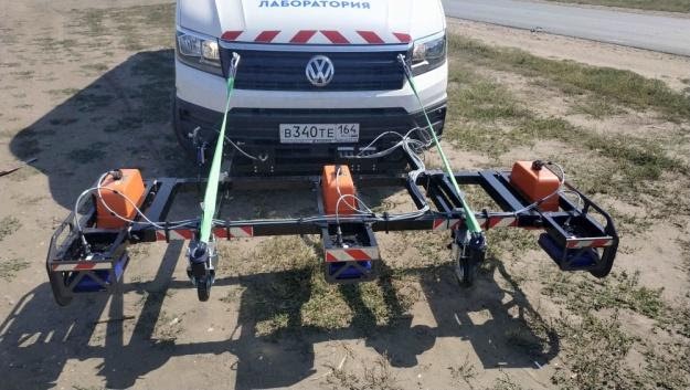
2. Vehicle version, when long sections of roads are examined, a specialized set of OKO-3 GPR equipment is installed on the vehicle.
Pedestrian scanning set
For pedestrian scanning, the antenna units indicated in Table 1 can be used, depending on the problem being solved.
Table 1

Antenna AB-400M


For scanning with sets installed on cars (road laboratories), the antenna units indicated in Table 2 can be used, depending on the problem being solved.
Table 2

Antenna unit AB-400R


Software for road inspection:
1. The GeoScan32 software is intended for scanning and saving sounding results from OKO-3 GPR. It is used for pedestrian scanning, as well as for scanning with vehicle sets in single-channel, 2-channel, and 6-channel mode.
2. The СartScan software is intended for scanning, saving and interpreting the results of sounding by the OKO-3 GPRs. It is used when carrying out scanning by a pedestrian method, as well as when carrying out scanning with vehicle sets in single-channel and 2-channel versions. The program allows:
• conducting GPR scanning using two different-frequency antenna units while viewing each channel separately, as well as the combined radarogram;
• working with all types of odometers and GPS-Glonass receivers;
• displaying trajectories of movement of antenna units on the map and plan;
• scanning in two-channel mode, viewing each channel separately, viewing the combined radarogram;
• editing trajectories obtained during scanning;
• building a three-dimensional model from the received data;
• processing the received GPR data;
• automatically laying out the boundaries of layers, as well as highlighting areas of high energy (humidity).
3. The Analysis7 software is intended for the interpretation of large volumes of sounding results by the OKO-3 GPRs. Features of the program include:
• the ability to compare the thicknesses of the layers laid on the radarogram with the restrictions set for them on the minimum and maximum thickness. Analysis of layer thicknesses can be performed simultaneously for several channels (interpretation of sounding results by several antennas);
• the output of the analysis results in the lower part of the radarogram in the form of colored stripes, which show the presence of deviations from the parameters specified by the customer: green – norm, yellow – on the verge of normative, red – non-compliance;
• possibility of highlighting places of high humidity on the radarogram. Moisture analysis can be performed simultaneously for several channels (interpretation of sounding results by several antenna units);
• the analysis results are displayed in the lower part of the radarogram in the form of colored bars;
• display of the thickness of structural layers with the specified restrictions on the minimum and maximum thicknesses, as well as the results of moisture analysis y in the form of colored bars;
• display in a tabular form of the thickness of layers at any selected point of the surveyed road surface;
• display of a radarogram on any selected section of the surveyed road;
• panorama view at the selected point.
About author:
Vladimir Kapustin
Ph.D. in Physical and Mathematical Sciences
Junior Researcher at the Moscow State University